Wireless Sensor Network, Part 1

With all components finally having arrived from China, I built the first couple of wireless sensors a few months ago. They are using the cheap nRF24L01 transceiver modules for data transmission based on the RF24Network network layer. I’m using a Raspberry Pi with the transceiver module directly connected to its GPIO pins as the root node. The sensor nodes are controlled by an ATmega328 microcrontroller flashed with the Arduino firmware for convenience.

Each sensor node currently features a DHT11 humidity sensor, a DS18B20 digital thermometer, a BMP180 barometric pressures sensor and it’s powered by three AA cells. The controller spends most of its time in power-saving sleep mode, waking up to send a data packet about every minute. Each packet contains the readings from the three sensors as well as the battery voltage as determined against the bandgap reference.

The setup is far from final. For one, I’m still not sure how to store the data. Currently, it is just logged into a text file with an occasional and experimental import into OpenTSDB. I haven’t really come to trust OpenTSDB since I haven’t found a suitable and convincing way to backup the HBase data, yet.  Also, I might still replace the Raspberry Pi root node with an Arduino based MQTT relay.

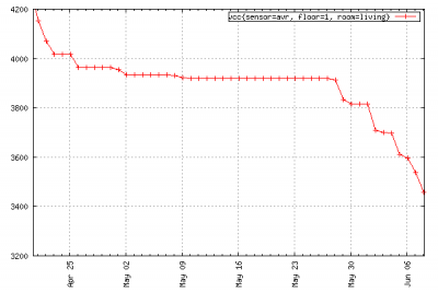
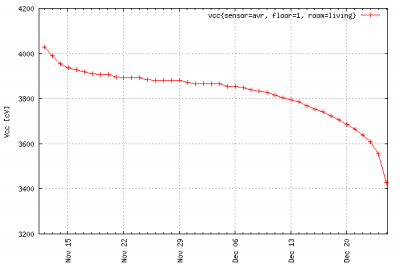
First though, the power consumption of the sensor nodes needs improving. When I started out I was hoping for each node to run for close to a year on a single set of batteries. As you can see in the graph above, with the current design a set of three NiMH batteries with low self discharge lasts for no more than 6 weeks. What comes to mind in order to improve this, is to switch off the sensors and the transceiver in between samples. That is probably what I’ll try next. Please let me know if you’ve got any other ideas!


Seeeduino Stalker: Writing to the SD Card

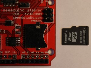
After I managed to upload the first sketches to the Seeeduino Stalker last week, I was eager to try the special features offered by this special kind of Arduino platform. I decided to try writing to an SD card first and followed the example included in the Stalker’s documentation. Which turned out to not work at all.

A couple of hours later and looking for errors in all the wrong places, I finally managed to find out how to use the FileLogger library:

  1. The SD card needs to be FAT16 formatted.
  2. The file that the the Arduino is writing to must exist 615-544-6598 , the library does not create files.
  3. The file must not be empty, it must contain at least one byte of data.

If these conditions are met, the following tiny sketch will work just fine and append data to the file:

#include "FileLogger.h"

void setup(void)
{
 byte buffer[] = "Hello World!";
 FileLogger::append("data.txt", buffer, 12);
}

void loop(void) {}

Update 10/8/12: Please note that this example will work with version 1.0 of the Stalker, only. For newer versions of the board you should try sadfatlib.

Connecting to the Seeeduino Stalker

A few weeks ago, Seeed Studio were celebrating their anniversary with a bunch of limited offers. Among other things, I acquired a pair of Seeeduino Stalkers v1.0 with an Atmega 168. Unfortunately, the serial interface on those boards is not labeled. So it took me a while to figure out how to connect the FTDI breakout board. With a small adapter board, programming the Stalkers with the Arduino IDE now works like a charm. (Select board type “Duemilanove w/ 168”.)

Waiting for my DSO Nano

I always wanted my own oscilloscope. Not that I really needed one or missed it more than a couple of times. But you can never have enough tools! What kept me from ordering one or from buying a used one online so far, was not so much the price. It’s the fact that the space I have to keep my tools is somewhat limited. A regular oscilloscope would be yet another big box standing in my way and gathering dust most of the time.

dso-nano-productThen, a few month ago, a post on hack-a-day pointed me to Justblair’s review on the DSO Nano. Justblair got his hands on one of the “beta test” models of the DSO Nano, a brand-new pocket-sized digital oscilloscope developed by Seeed Studio. While it has a few limitations and draw-backs, it’s size and the price tag of only $89 do make it a really interesting option. When I checked back two weeks ago, I noticed that Seeed Studio was accepting pre-orders for the final version of the DSO Nano to be shipped on December 10th. So I had to order one.

The probes that come with the DSO Nano are supposed to be rather basic, which is alright at that price. Seeed Studio offers a BNC adapter, allowing standard probes to be connected to the DSO Nano. Unfortunately, the adapter was sold out the day that I placed my order. When it was back in stock a couple of days later, I sent an email, politely asking if they could replace the spare probes that I had ordered with one of those adapters. They are both the same price. My email was answered quickly, and Xiang Fan promised to update my order. Great customer service!

By now, the DSO Nano seems to be ready, and the shipping seems to be in progress. I can’t wait to try it out. But it probably won’t make it all the way to Germany before the beginning of next year. Well, you always need something to look forward to.

Making a XU1541 Cable

I have been documenting interesting software and programming related findings in my own private Wiki for a few years now. This turned out to be really useful in many cases, especially on topics that I would run into only very infrequently. Most of these notes would not be of any interest to anybody else but me, while a few of them might be worth offering to a wider audience. All it would take would be some nice presentation and a little effort to write things down in whole sentences. Or so I thought.

IMG_4934b.JPG

The finished XU1541 adapter.

When I began tinkering with electronics again, I soon decided this would be a great excuse to start my own blog, sharing my progress. After my initial enthusiasm had worn off, I soon realized that I had somewhat underestimated this project. It takes a good deal of time and effort to write things down in whole sentences and to present them nicely. As a result, there are a few projects that I finished this year that I failed to put up here so far. Most likely, I have forgotten a lot of interesting details by now. But I’ll try and summarize what I do remember.

Continue reading

Making a XA1541 Cable

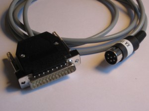
As you might have read in my previous post, I retrieved  my old Commodore hardware from the attic and found it still working. Even most of the 5 1/4″ floppy disks that I inserted into one of the squeaking 1541 drives seemed still readable. So, I decided this might be the last chance to save those very early lines of code from oblivion that I had written so many years ago. Not that it was really worth it, it’s mostly a matter of principle to not let a single bit of code get lost if I can help it. To convert what was still readable to d64 disk images, I first needed to make a suitable adapter cable.

The XA1541 seemed like a good choice to start. It’s an adapter to connect the Commodore 1541 disk drive to the parallel port of a PC. While there are other solutions, the XA1541 seemed easy enough to build and reported to work with most (all?) parallel ports found in today’s PCs. If there is a parallel port to be found at all. We’ll cover that in a later post on making a XU1541 cable, though.

Also, there are excellent instructions by Stefan Uhlmann on how to make one of these. The page is available in German only but very well illustrated.

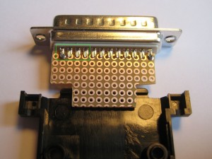
All that is needed are two connectors (obviously), a length of shielded wire, four resistors, and four transistors to drive the interface. Just as Stefan suggested, I wanted to fit the active components onto a small piece of prototyping board inside the D-sub casing of the parallel port connector. The first step is to cut the board so that it will fit into the casing while still leaving as much room for the components as possible.

xa-1541-step1

Fitting the board into the connector’s casing.

The board fits smoothly between the two rows of the D-sub connector, and the connector is then soldered directly onto the board. The lead-wire spacing of the connector does not match that of the prototyping board, but that doesn’t matter. Only the four left most leads 14-17 of the connector, marked with a green box in the picture, must not be shorted. The other leads 18-25 on this side get all connected to GND anyway.

Solder the d-sub connector to the board.

Do not shorten pins 14 – 17.

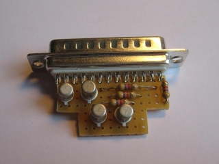
Next, I placed the four resistors and transistors on the board and fixed their wires with soldering points.

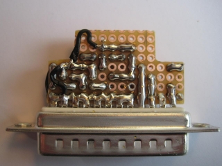
It really helped and saved time to have Stefan’s images as a guideline. Since I placed the components exactly where Stefan did, all I needed to do then was to spread solder onto the copper side of the board until the shiny pattern looked like the one on Stefan’s picture.

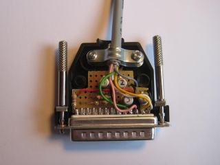
Finally, the the leads from the shielded wire are attached and everything gets stuffed into the D-sub connector’s casing. The DIN connector fitting into the Commodore IEC serial bus is soldered to the other end of the cable and we’re all done.

The XA1541 is ready to connect our trusty 1541 drive to our PC. Using a great piece of code called OpenCBM (formerly known as cbm4linux) we are now able to access the data from the 5 1/4 inch disks.

Prologue

My soldering iron, my collection of spare electronic components and related tools had been stored away in the basement for years. Way back, I really enjoyed tinkering with those, but when I decided to go for the software engineering aspects of computer science I somewhat lost interest. So many things to try and so little time to spare. Also, I have been lacking the room to set up a suitable work space.

My old soldering iron.

As with many other IT people of my age,  my first “real” computer was a second-hand Commodore 64 that my parents bought for me in the mid-eighties. I absolutely loved that machine and spent countless hours in front of it, teaching myself it’s Basic and Assembler dialects. Even though I bricked the C64 a few years later, trying to install a self-designed relay card and replaced it with a C128, I could not bear parting from the Commodore hardware. So I stored the computer and it’s peripherals in card board boxes in the attic many years ago.

Spring 2009: By chance I stumbled across Ben Heckendorn’s blog where he describes how he created his Commodore 64 original hardware laptop. I really admired his work and I really wanted such a portable for myself! Ben integrated a 1541-III DTV into his construction to replace the traditional 1541 floppy disk drive, which of course would not have fit into the laptop. Using the 1541-III connected to the normal serial bus of the C64, it allows you to mount and read d64 disk images from ordinary MMC or SD memory cards. Awesome!

Googling around, I discovered that by now there are actually several different solutions that offer this feature. There are the afore mentioned “cousins” 1541-III DTV and 1541-DTV, both based on PIC micro-controllers. The design has later been ported by Lars Pontoppidan to an AVR micro-controller, which he called the MMC2IEC. The MMC2IEC hardware and firmware has been extended and improved by a bunch of other people and evolved into the SD2IEC. Finally, there is the 1541 Ultimate that reportedly does a good job of fully emulating the original 1541. As a result, it should be able to support even copy protected games and other software that comes with their own fast-loader routines. Unfortunately, the 1541 Ultimate is also rather expensive.
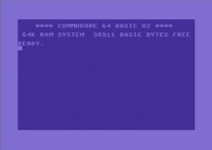
C64 start screen

AntaBaka has done a great job of collecting and summarizing the evolution of the SD2IEC on his page, which is available in German only, though. It was when I read that page that I decided I wanted to build one of those SD2IEC myself. It would be a nice project to play around with the AVR micro-controllers that I kept reading about for some time on sites like Hack-a-Day and Makezine. And it would be a great excuse to dig out the old stuff I had hidden in basements and attics.

I also liked the idea of trying to save my old Basic and Assembler programs from oblivion, petty as they might be. My old discs had been been stored in the attic along with the hardware. They had to endure extreme heat in summer and cold temperature in winter for about 15 years. Would there be anything left to save? Or would even the disk drives be decayed and broken by now? To cut at least that long story short: my trusty old C128 was working fine when I pulled it from it’s card box. And the two 1541 were happily loading the randomly chosen disks I tried them with.

So, the first step would be to get the data from those discs and store it in d64 disk images on my PC’s hard drive. There are a bunch of different cables and adapters that can be used to accomplish this. The xu1541 appealed most to me because it is “legacy free” (what irony!), bridging between the USB port and the Commodore IEC serial port. Also, it is based on an AVR micro-controller.

But at first, I was a little afraid I could be wanting more than I could handle. So I decided to revive my tinkering in electronics with the simpler design of the xa1541 adapter which connects the 1541 disk drive to the parallel port of the PC. We’ll hear about that another day.