Last year, I acquired my first VIC-20 and when I discovered that someone shared the Gerber files for a fairly recent version of the Final Expansion 3 (english) for that machine on Github, I decided to set out and build one of those, of course. The FE3 might be a story for a later post, though. Because in order to build that cartridge, I first had to find an affordable way to program the ATF1504 CPLD that is used here.
The ATF1504 has a JTAG interface and that was the obvious choice for the task. I had a CJMCU (?) FT232HQ breakout board (from eBay) lying around that I had used before together with OpenOCD to successfully program the Xilinx CPLDs used in the replacement PLA.
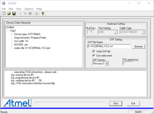
First though, I had to convert the JED file for the CPLD into a SVF file that I could then play over the JTAG interface. After some research, more trial-and-error and a little help from the folks at Forum64, I learned that this could be done using the ATMISP tool provided by Atmel.
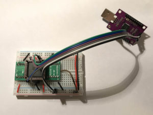
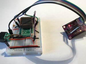
Next, I whipped up a temporary adapter on a breadboard and tried to write the resulting SVF file to the CPLD using different players — with no success. After some time spent debugging my setup, I ordered additional ATF1504 ICs from a more reliable source. With these, I was finally able to program the CPLD using OpenOCD:
bin-x64\openocd.exe -f scripts\interface\ftdi\um232h.cfg -c "adapter_khz 400" -c "transport select jtag" -c "jtag newtap ATF1504AS tap -irlen 3 -expected-id 0x0150403f" -c init -c "svf VC20FINAL-V3-2.svf" -c "sleep 200" -c shutdown
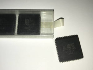
It turned out that the devices from the first batch that I received weren’t quite as new as the seller had claimed. They had been used before and probably programmed in a way that disabled the JTAG interface. Luckily, I received another reply on Forum64 hinting at a way to bring those ICs back to life.
Though (almost) not documented in the datasheet, the OE1 pin of the ATF1504 doubles as Vpp. According to the author of the post, applying 12V to that PIN through a current limiting resistor would reset the JTAG functionality. So I added a 12V power supply to the breadboard contraption and created another SVF file to erase the CPLD, again using ATMISP. And indeed, with 12V on OE1 I was able to erase the used ATF1504!
bin-x64\openocd.exe -f scripts\interface\ftdi\um232h.cfg -c "adapter_khz 400" -c "transport select jtag" -c "jtag newtap ATF1504AS tap -irlen 3 -expected-id 0x0150403f" -c init -c "svf atf1504as-erase.svf" -c "sleep 200" -c shutdown
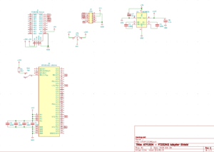
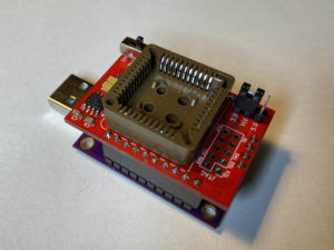
In order to be able to reproduce all of this later more easily, I decided to write this blog post and I moved on to create a custom PCB that would replace the breadboard adapter and plug as a “hat” onto the FTDI board.
I had to wait quite a while for the last components to arrive, but then I was able to successfully assemble and test the ATF1504-FT232HQ Shield. It features a MAX662 boost converter to produce the 12V programming voltage on-board.
As usual, the project files for the adapter board are available on Github. Finally, a big thanks to the ever helpful crowd on Forum64 who guided me along the way!



Hi,
bei microchip ist ATMISP nicht mehr zu finden … kannst du das tool auf github hochladen? danke!
Well, no, for obvious reasons I cannot upload proprietary software to Github. But it is really easy to find it on Microchip’s site if you use a search engine: https://www.microchip.com/design-centers/fpgas-and-plds/splds-cplds/pld-design-resources
Thank you for your project
Can you give your version of openocd. With the last version (OpenOCD 0.10.0 ), I don’t have the same syntax and it’s not working
Thanks
Sure, I’ve been using OpenOCD version 0.10.0-rc2.
I have encountered the same problem when I try to program a ATF1502, I have used Altera USB Blaster and UrJtag. After connecting OE1 to 12 volt the chip back to life! I’m be able to program only 1 chip of 2, one not respond at all even if I use the above trick, anyway thank for the help!
This works great, it took some hours to figure it all out but now it works great!
thank you for releasing this project for free for people to use, helped me alot and salvaged 18 ATF1502AS that i could not program before! (cheap aliexpress :p)
What type of capacitor are you using for C7 and C8. Seems to be a KEMET one. If I open the KiCAD file it says it should be a SMD 1206 (3216 metric). But I couldn’t find one at the usual suppliers.
Looking at the schematics again now, I noticed a typing error: both C7 and C8 should have 4.7uF as described in the datasheet for the MAX662A. Maybe, this is already what you were struggling with. I used polarized tantalum caps but I can’t tell anymore where I got them from. They should be easy enough to find though, e.g. part no. “T491B 4,7U 20” at Reichelt.
I’ve tried to program my svf file to the ATF1504AS. I get the following message:
Open On-Chip Debugger 0.11.0 (2021-03-07-12:52)
Licensed under GNU GPL v2
For bug reports, read
http://openocd.org/doc/doxygen/bugs.html
adapter speed: 400 kHz
jtag
Info : clock speed 400 kHz
Info : JTAG tap: ATF1504AS.tap tap/device found: 0x0150403f (mfg: 0x01f (Atmel), part: 0x1504, ver: 0x0)
Warn : gdb services need one or more targets defined
svf processing file: “Z80_512K.svf”
Time used: 0m0s0ms
svf file programmed successfully for 0 commands with 0 errors
shutdown command invoked
What does the warning mean. Is the CPLD programmed? I cannot find any target definitions for the ATF1504AS within OPENOCD.
I am not exactly sure what the warning means, but I’m also getting it and it does not matter for our simple flashing purposes. The rest of the output you are getting from OpenOCD looks good, too. Except for the part saying “0 commands with 0 errors”, which probably means that your CPLD has not been programmed.
Hi,
Do you have any of your F232HQ shield boards lying around? I’m trying to work out what I need to program the ATF1504 for the same Final Expansion 3 project and am struggling a bit 🙂 I have a TL866 II programmer, a GQ4x4 programmer and a Waveshare DLC10 Platform Cable USB CPLD/FPGA programmer but none seems to be able to program the ATF1504. I saw your project here and thought I might reach out to you to see if you have anything left over when you made your hats up?
Cheers,
Mark.
I’m almost certain that I still have a few of those PCBs lying around. But unfortunately, I also suspect that shipping to the UK might be more expensive that having 5 more of them made and shipped from China…
Ahh – you’re not in the UK? That’s a pity.. I generated the gerbers from the github you have setup but jlcpcb tells me that there’s an error with them.. not sure what it is..
Could you generate the gerbers from your latest design and email them to me, if that’s not an imposition?
Many thanks,
Mark.
I have also shared this project on PCBWay. So, if you don’t mind using them instead you could order the PCBs directly.
Hello, I am trying to program my atf1504as, could you tell me if the CJMCU FT232HQ has to be configured first before connecting it to the atf1504as, my chips also have the jtag blocked but I can’t unlock them with the 12v in the OE1, thanks.
Great job
No, I did not have to configure the FTDI-Module in any way. As far as I know, all the necessary configuration is volatile and taken care of by OpenOCD. Maybe your chips aren’t just locked but actually broken?
Pingback: MSX-USB - The Retro hacker
Pingback: Building the RBSC MultiMapper – The Retro Hacker
Thanks for sharing your project.
I tested atf1504as plcc84 bought from Aliexpress.
After soldering both the CPLD and Flash memory, it burned out when I turned it on.
Yes, they sell used stuff.
I soldered only CPLD to another PCB and connected 12V to OE1 using a cheap DC-DC step-up converter. ( https://aliexpress.com/item/1005003203922131.html )
It failed with 2k and 1k ohm resistors because the voltage drop was too large.
I succeeded by connecting directly with no resistor.
Thank you again.
Complete n00b question. I’m wondering why you didn’t use WinCUPL rather than OpenOCD. WinCUPL is available on the same download page as ATMISP. Does OpenOCD have some capability that WinCUPL lacks? Or am I missing something else?
As I said, I had used OpenOCD together with the FT232HQ before to program the Xilinx CPLDs, so that was my best guess. Maybe you can use WinCUPL for the job, maybe it’s even easier — I don’t know. Please report back when you’ve tried, I’d be curious to learn.
Thanks! I will!
If you’re tracking backlinks, I gave this article a mention on my site:
https://www.devastatia.com/thread-26-post-669.html#pid669
Thanks for the very informative blog article. I’ve got an ATF1508 CPLD and I’m hoping to use your technique to program it. Do you know the right OpenOCD command-line that I could use? Cheers!
Hi there, I’ve been building a Final Expansion 3 as you were for this article, and I’m not a programmer or developer or anything. I’ve been trying to follow your outline, but I seem to be stuck on the OpenOCD command. Using what you use – [openocd.exe -f scripts\interface\ftdi\um232h.cfg -c “adapter speed 400” -c “transport select jtag” -c “jtag newtap ATF1504AS tap -irlen 3 -expected-id 0x0150403f” -c init -c “svf VC20FINAL-V3-2.svf” -c “sleep 200” -c shutdown] – just seems to end in “gdb services need one or more targets defined” and nothing actually happening.
I’ve tried the most recent version of OpenOCD (0.12.0) as well as “0.10.0-15”, but they both have identical issues. I couldn’t find a binary download of 0.10.0-rc2, as you say you used here in the comments.
I’ve got all the rest of the cartridge all built; the specific syntax of a command line feels like such a small thing to be holding the entire project up, but it’s such a hurdle trying to investigate what it ought to be.
Any pointers?
Thanks.
I‘m traveling at the moment so I can’t check. I‘ll try to remember to get back to you on this.
Oh great to hear, I look forward to it.
Thanks.
Oh, I’ve realised I’ve been foolish.
This isn’t your fault at all, but rather me being oblivious.
The “gdb services” warning was a red herring; the real symptom was that it kept showing me the guide to formatting the “svf” command…
The file I had was, as one would expect, “VIC20FINAL.V3-2.svf”
Because of my inexperience, I’d simply copied your command into the command prompt (merely changing “adapter_khz” to “adapter speed” since OpenOCD explicitly directed me to).
However… in the command you use, you spell the filename “VC20FINAL-V3-2.svf” No letter I between the V and the C!
And I think because it was all capitals, I is a slender letter, and it was all a lot to get my head around, I’d convinced myself I was seeing the filenames as identical!
Having now addressed that discrepancy, it now seems to have done the programming just fine, and I can finally test my build, and not have to shell out for the special programmer cable!
So, for clarity and ease for others:
Using Windows, and OpenOCD 0.12.0,
– I placed the VIC20FINAL.svf file created earlier in your guide into the OpenOCD “bin” folder where “openocd.exe” is,
– Moved the OpenOCD “scripts” folder into this “bin” folder as well,
– Opened the command prompt directly in the “bin” folder,
– Then used this command exactly:
openocd.exe -f scripts\interface\ftdi\um232h.cfg -c “adapter speed 400” -c “transport select jtag” -c “jtag newtap ATF1504AS tap -irlen 3 -expected-id 0x0150403f” -c init -c “svf VIC20FINAL-V3-2.svf -progress” -c “sleep 200” -c shutdown
(I just added “-progress” to be a bit friendlier if it took a long time!)
I hope that perhaps my embarrassment can be a help to others who might be following this for themselves in the future. Seemed to be some others caught up on using the command – perhaps they’d overlooked the same thing.
Thanks for the very helpful guide!
Absolutely no reason to feel foolish, quite the opposite. Congratulations on solving the problem! In Germany, the VIC-20 was actually labelled VC-20 because of the possible phonetic similarity of “VIC” to a German word not suitable for mainstream marketing. 🙂
But now that you have mentioned the version number of this file, I have to drop another hint: Just recently, the creator of the FC3 and I tracked down a bug in the original design that would mainly affect NTSC-based machines. It requires a bodge wire on the PCB and firmware version 3.3.2 to fix. See e.g. here for details.
Oh, that’s good to know about! I have a PAL system, but I’ll look into it for sure. Thank you very much again!
Thank you, this is excellent!
I integrated what I learned from this article and a reference to your GitHub repo into a VS Code plugin, VS Cupl.