Update 2018-05-25: Now that revision 1 is confirmed to be working despite a couple of minor issues, here’s the rev.1 Gerber files for download. Bear in mind though that the improved 2nd revision is under development and will be available soon!
Two weeks ago, there were exciting retro-news on the Lemon64 board: Gorack – aka. Steve White – released the first version of his Pi1541 that he had been working on for quite some time. “Pi1541 is a real-time, cycle exact, Commodore 1541 disk drive emulator that can run on a Raspberry Pi 3B (or 3B+).”
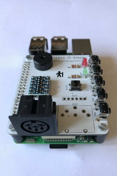
I was curious and wanted to give this a try, but I also wanted proper wiring. So I created my own version of an extension board for the Raspberry Pi. (Not a proper “HAT”, that would require an eeprom and other things.) I then ordered a small prototype batch because others were eager to try our new retro toy, too.
I received the PCBs on Friday after some unfortunate delay at the German customs and by now the first board is assembled and seems to be working fine!
There are two minor issues in revision 1 that I will address in revision 2:
- The drill holes for the level shifter module should be a tiny bit wider. Regular pin headers only just fit and one has to be careful not to damage the board.
- Maybe the wiring of the power LED is too simple. It will glow faintly even with only the C64 powered on, obviously drawing current through the bus.
Also in revision 2, I’m adding optional support for a TXS0108 level shifter module to be used instead of the simple, BSS138 based one. There has been some concern that multiple, additional devices attached to the IEC bus might damage the Raspberry Pi when using the simple level shifter.
This is what you need to fully assemble one of the revision 1 PCBs:
| 1 | P1 | 2×20 pin female header | eBay |
| 1-2 | IEC1-2 | 6 pin DIN socket | eBay |
| 5 | SW1-5 | right-angle push buttons | eBay |
| 1 | U1 | 4 channel level shifter module | eBay (China) eBay (Germany) |
| 1 | SW6 | push button (optional) | eBay |
| 1 | D1 | 3mm green LED | |
| 1 | D2 | 3mm red LED | |
| 1 | R1 | resistor 330Ω | |
| 1 | R2 | resistor 220Ω | |
| 1 | piezo speaker (optional) | ||
| 4 | M2.5 screws, 18mm | ||
| 4 | M2.5 nuts | ||
| 4 | distance rolls, 11mm |
In addition, you’ll need a Raspberry Pi 3B or 3B+, a micro SD card, a good power supply, and a Commodore serial cable.
The KiCAD project and the Gerber files will be released soon.


Pingback: Pi1541io in between Revisions | hackup.net